
Jim's Woodworking Shop
My Homemade Antenna
Click on pix for a larger view
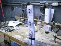 I used the basic TV Antenna Plans but, with some modifications. Here is the completed antenna with my modifications. The basic plans called for mounting the elements right on the wood base, however, wood, even with a coat of paint, collects moisture, and would be an un-necessary resistance across the elements. Some of the early outside TV antennas used plastic mounts for the elements. That's what I did here.
 To the left is a closeup of the plastic element mount. They are 2 x 2 1/2".The chamfered holes are for the #8 x 1 1/2 wood screws. The other holes are for the 6-32 bolts to hold the elements.
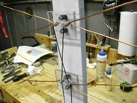
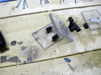 Here is a closeup of the mounting hardware. The black spacers are pieces of rubber automotive tubing I happened to have laying around. anything could be used, even a 1/2 stack of washers. Probably, the less metal you have in the vicinity of the elements would be better.
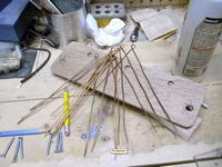 The elements are made from copper house wiring that I had laying around. I bent them around a drill to form the eyehole to mount them. I didn't worry about the 3" spacing of the ends, as when they are mounted they can be bent to the proper spacing very easily. The small washers go under the head of the bolt to better secure the elements.
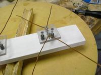 The elements are mounted on the plastic but, they don't have the wires run yet, so nothing is tightened up.
 This is a detail of the wiring. I used some black insulated bell wire I've had for years. Any wire will do. I found it works very well to strip the end of a length of wire about 3/4", then wrap it around the bolt, under the washer, and on top of the element. Tighten it down, and then measure to the next element and carefully strip the insulation for that connection. If you can do this without cutting any of the wire strands, it's good. Notice that the wire crosses over to the opposite side, then drops straight down to the next element, then crosses over to the last element on the side you started on. It's very important that it be wired this way. If perchance you use bare wire, where they cross must be insulated from each other.
 After the elements are all wired, the 300 ohm twinlead wire attaches in the very middle of the feed wires. The plan shows the balum attached here, and coax running to the TV, however, in my situation, the flat twinlead will go right under the screen and window into the house. The round coax would be a problem. So, I elected to attach the balun to the twinlead inside the house. From there I have the round coax running to the TV.
 The final picture shows the antenna mounted outside. I put an eyebolt into the end of the 3/4 wood base, and hung it on a nail that was in the eave of the house. In the Jacksonville area I now get 25 channels, and most of them are at 85 to 97% signal strength. I'm amazed at how well this little jewel works. I estimate if a person had to buy everything to make it, you might put $20 - $25 into it. To me, that's a good investment, especially to be able to say, "I made it myself".
On the website, the question was raised: "Would two antennas work better than one?"
Well, the antenna for our main TV didn't seem to work as well as the one on the Converter Box in the bedroom. I tried changing them around and it made no difference. So, either the bedroom antenna is in a better location, or the Converter Box is more sensitive than the TV. Maybe a little of both.
So, I made another antenna and hooked them together at the joint where the thick twinlead hooks to the thin twinlead that goes through the window. I tried them both ways, and Phase does Matter! With the wires hooked one way I have a signal strength of 20, with them the other way, the strength is 26 on the weakest station.
(2014) We have since this was first written changed the TV in the living room, and I discovered the TV with the converter box wasn't getting some of the far channels. So, it now has a little dandy RS amplifyer attached. It helps quit a bit. Also, the run of the mill screws and washers don't stand up well around here. Stainless would be a better choice.